Issues with Spatial Reference Systems
Introduction
You have been asked to perform spatial analysis in Humboldt County and are provided with data layers from different sources. Before beginning your analysis, you must document your data, troubleshoot issues with spatial references, and make sure all data is projected into an appropriate spatial reference (coordinate reference system).
Note: These data represent real problems that occur with GIS data and that the instructors have seen over and over again. We've created this dataset to help you learn how to work through these issues.
Learning Outcomes
- Create a file structure for working with spatial data on a project
- Recognize and address problems with undefined and incorrect spatial reference systems (CRS/SRSs)
- Use Project and Define Projection tools in ArcMap
- Locate and read metadata (from web, text file, xml)
- Use a standard QAQC process
Data
QAQC Form - Forms to complete for each data set.
Lab 3 Data - The data you will be checking.
The data contains the following:
- 24k Topographic Map
- Humboldt County Boundary
- Federal Land
- Alaska State Boundary
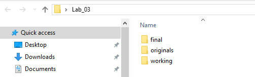
Walk Through: Setting up your Workspace
- Set up your work space the way you did in lab_01.
- In your “Working” folder, create a subfolder named “WGS84_UTM_Zone_10”. We will use this for our projected files later.
- Right-click on the “Lab 3 Data” link above, and click “Save As.”
- Navigate to your "Originals" folder in your workspace and save the zip file.
- Unzip the data: Right click on the "zip" file and select "7-Zip -> Extract Here"
Once the files have extracted successfully, you can delete the zip file.
- From the ArcCatalog window, drag the 24KTopo.tiff file into the Table of Contents within ArcMap. If asked about creating pyramids, click Yes.
- For this lab, you are going to assume that there are no Spatial Reference issues with this USGS topographic map.
- Now drag the rest of the data into the Table of Contents, writing down the heading of any error messages that appear and the name of the data it is associated with.
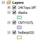
You may notice error messages appear as you drag and drop new layers into the data frame. These will be addressed later, so for now, just take note of them and close them by clicking “close”. You should end up with 4 layers total in the data frame.
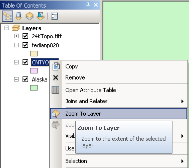
The Table of Contents should look similar to this:
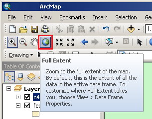
- Use the “Full Extent” button in ArcMap to zoom to the extent of all your data.
- Right-click on the “CNTYOUTL” layer and select “Zoom to Layer”. This zooms to the extent of the selected layer only. Try this for all of the layers.
- Move your cursor around the data frame and notice the coordinates displayed in the lower right portion of the window. Think about if the coordinates make sense based on your knowledge of geographic data and projected data?
Walk Through: Document the Data
Analyzing documentation is a very important step when working with data.
You will now start documenting the Humbodt County Dataset
- Open the Quality Assurance/Quality Control (QAQC) form and read through the instructions. You will fill out this form electronically.
- Save a copy of the PDF as “CNTYOUTL_QAQC” into your "Originals" folder and begin filling it out as follows:
Downloaded data often comes with associated metadata. It is important to explore this data. If no additional data is provided, contact the entity you downloaded the data from for this information.
- Give the dataset a descriptive name, such as “Humboldt County Boundary.”
- The File Name is the original downloaded file name, “CNTYOUTL.shp.”
- The Source is the location the file was downloaded from. Also include any information on the organization that originally created the data such as their name and URLs.
- The General Location is Humboldt County, CA.
- The Collection Method may be documented in the metadata, if not, leave this feild blank.
- Contact Information might include names of people to contact, email addresses and/or phone numbers and is typically found in the metadata.
- Right-click on the CNTYOUTL layer in your Table of Contents and select “Layer Properties”
- Note the File Format and Data Type (labeled "Geometry Type"), and current spatial reference are listed under the “Source” tab.
We need to check our data against a known source to make sure that it is in the correct spatial reference system. A digital raster graphic (DRG) is a scanned USGS topographic map that is georeferenced to the earth’s surface.
- Explore the 24KTopo TIFF image and note the spatial reference system in the properties.
- Double-click on the CNTYOUTL layer in the Table of Contents to bring up the layer’s properties. On the “Display” tab, set the transparency of the layer to 50%.
- With the CNTYOUTL layer displayed above the 24KTopo, check that the CNTYOUTL layer is using the correct spatial reference system, and record this on your QAQC form.
- Record any notes about your data and complete the “Review Information” section.
- Complete any other entries in the form that you can and check page 2 of the form for additional information.
- Save your edits to the form.
Skill Drill: QAQC Forms in Groups of Two
- Complete QAQC forms for the remaining data sets. Note any problems you encounter. You are encouraged to do this in groups of two and check each other's work. If the current Spatial Reference is missing or incorrect, find out what it should be by looking through the documentation that came with it. The the most common places to find what the CRS/SRS should be are:
- The website where you downloaded the data.
- The associated .txt file that came with the data.
- The associated .MET file that came with the data.
Walk Through: Changing the Data Frame's Spatial Reference
If subsequent layers are added with CRS/SRS that differ from the Data Frame's CRS/SRS, ArcMap will “project on the fly” to display all layers in the same CRS/SRS as the Data Frame. This can noticeably reduce the performance and speed of ArcMap and produce inaccurate results. When completing spatial analyses, we want all of our data to be in the same CRS/SRS to get accurate results and speed up processing time.
- Double-click on “Layers” in the Table of Contents to bring up the properties for that data frame.
- Under the “Coordinate System” tab:
- Select Projected Coordinate Systems → UTM → WGS 1984 → Northern Hemisphere → WGS 1984 UTM Zone 10N
- Click “OK.”
- You may get a warning stating that all of your layers are not in the same CRS/SRS. We will address this later, so click “Yes” for now.
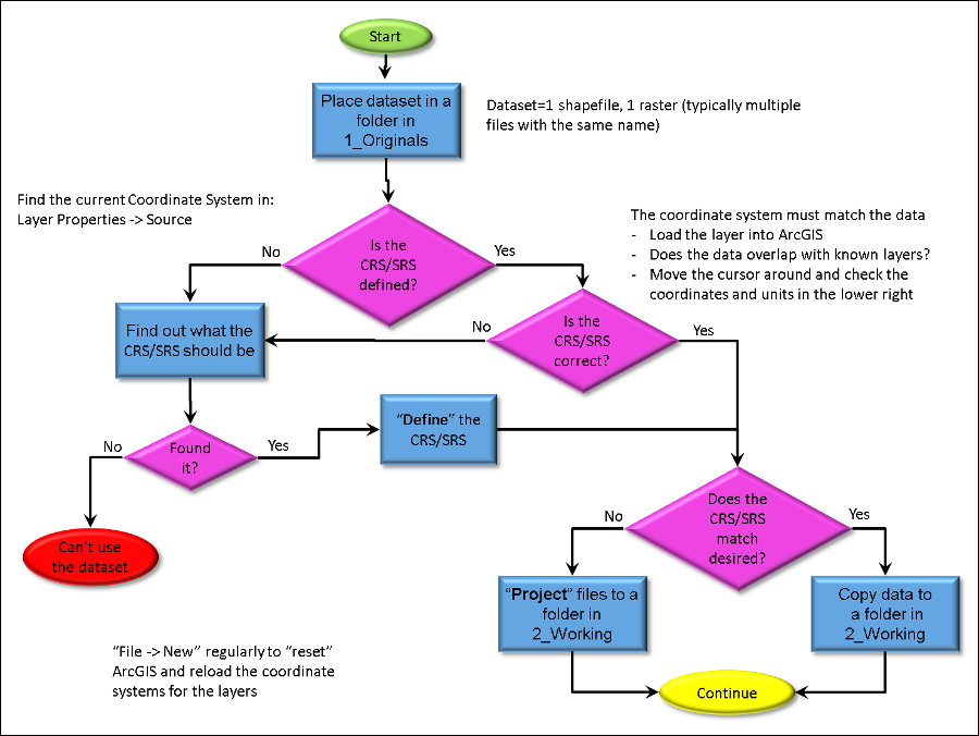
Walk Through: Project vs. Define Projection
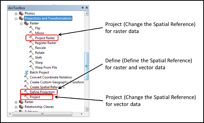
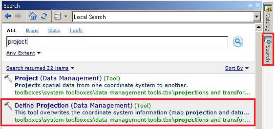
There are two types of tools that are used when handling the CRS/SRS of spatial data: Project and Define Projection. These can be accessed by using either ArcToolBox, or the Search tab.
- The ArcToolBox window for version 10.2.2 is shown below with the "Define" and "Project" tools identified. Note that the tools may be in slightly different locations and the names may change a bit in other versions of ArcMap.
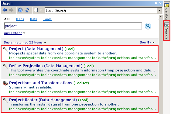
- To use Search tab: type in “Project”.
- Click on "Project (Data Management) (Tool)"
"Project" and "Project Raster" are essentially the same tool, but "Project" only works with vector data, while "Project Raster" only works with raster data.
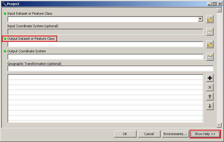
- Click on “Show Help” in the Project window.
A key difference between the Define Projection and Project Tool, is that the Project tool outputs a NEW dataset each time it is used. This is because the Project Tool allows you to specify a new CRS/SRS without modifying the original data.
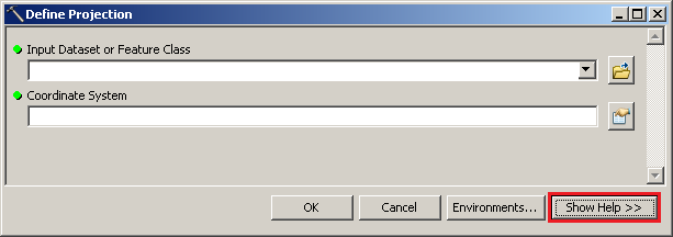
- Now, go back to the search results and click on the "Define Projection (Data Management) (Tool)" and read the help for this tool, as well.
Upon closer inspection of the Define Projection tool, you should notice that there is no OUTPUT dataset. This is because the Define Projection tool overwrites the original CRS/SRS of your data. It is VERY important to understand the difference between overwriting a CRS/SRS and modifying it into the form of new data. If you overwrite the original data's CRS/SRS into the incorrect CRS/SRS, the data will not be assigned with the correct position on earth. This tool works for both raster or vector data.
Question 1: Under what circumstances would you use the "Define Projection" tool?
Question 2: Under what circumstances would you use the "Project" tool?
Skill Drill: Spatial Reference Correction
Now that you have documented all of your data, use the topics below to address specific issues with your data. Make sure the data frame is set to the CRS/SRS you want to use.
Undefined CRS/SRS
When a layer does not have a defined CRS/SRS (i.e. the original CRS/SRS cannot be found), the following message will appear:
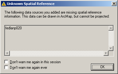
This means you will need to find out what the CRS/SRS should be.
Warning: Never check the boxes "Don't warm me again in this session" or "Don't warn me again ever". You want to know when your data is not referenced to the same CRS/SRS.
- If already completed, refer to your QAQC form for this dataset. Otherwise, look through the documentation that came with your data. The the most common places to find what the CRS/SRS should be are:
- The website where you downloaded the data.
- The associated .txt file that came with the data
- The associated .MET file that came with the data
- If you have located the CRS/SRS, define it using the Define Projection tool.
Incorrect CRS/SRS
If you notice that the data does not appear to be correctly positioned on earth, but has a defined CRS/SRS, your data has an incorrectly defined projection (i.e. the original CRS/SRS is wrong).
- Qualitatively determine if the shapefile has an incorrectly defined CRS/SRS using the USGS Topographic map provided.
- Repeat steps 34 and 35.
Question 3: What would cause Alaska to appear top of Humboldt County? How do we remedy this problem?
Skill Drill: Projecting to the desired Spatial Reference
Now that you have finished correcting the CRS/SRS of data with either undefined, or incorrectly defined CRS/SRS, it is time to project all of the data into the same spatial reference using the Project Tool.
Different CRS/SRS
When you add data to a data frame that uses a different CRS/SRS, the following message will appear:
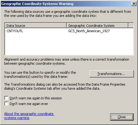
Project data into the same CRS/SRS as the data frame by using the Project or Project Raster tool to make this dialog stop appearing, and to avoid any of the issues that come with "projecting on the fly."
Warning: Never check the boxes "Don't warm me again in this session" or "Don't warn me again ever". You want to know when your data is missing a CRS/SRS.
- Open the Project Tool.
- Under "Input Dataset or Feature Class," select CNTYOUTL from the drop down menu.
- For your “Output Dataset”, navigate to the “WGS_1984_UTM_Zone_10N” folder you created in your “Working” folder.
- Add _WGS84_UTM_10N to the original filename (i.e. CNTYOUTL_WGS84_UTM_10N).
- Set WGS_1984_UTM_Zone10N as the Output Coordinate System.
Tip: if you are going to access a specific CRS/SRS multiple times, add it to your “Favorites” folder by clicking on the “Add To Favorites” button – it looks like a star with a plus sign on it.
- For now, you can leave “Geographic Transformation” blank and let ArcMap use the default. If an transformation is needed, refer to this PDF on how to select the transformation for the datums your are using and the area of interest.
- Repeat this process to project all data that is not in the same CRS/SRS as the data frame. Remember to use the Project Raster tool for raster data.
Question 4: Once you have used the Project Tool to project your data to a new CRS/SRS, you may not notice a difference between the new layer and your original layer. Why do you think this is?
Hint: it was discussed earlier in the lab.
Question 5: Which, if any, of these data sets are not appropriate to use for an analysis in Humboldt County? Why or why not?