Spring 2018, GSP 330 Final Practicum
Assume that the College Creek Soccer Field is going to be converted into a children’s playground. There is a rough plan (figure 1) for the proposed layout but the real positions of the features will depend on the current conditions, i.e proximity to existing features such as roads, sidewalks, trees and buildings. You are going to take into account factors like the children’s safety and noise levels in designing the final layout. Your task is to follow the instructions below and design a basic survey protocol that will allow you to stake-out the features in real-time in the field and create a map that shows the final layout. Your data should be collected and presented in WGS 1984 UTM Zone 10N projected coordinate system.
As a team:
The first task is to create a data dictionary that you will use with Terrasync in the field. Create a data dictionary for the following features and attributes and transfer it to the Trimble Mobile Devices.
Feature |
Feature type |
Attribute |
Attribute type |
Alias/description |
Starting point |
Point |
Recorder |
Text |
Name of surveyor |
Merry-go-round |
Point |
Recorder |
Text |
Name of surveyor |
Flag spot |
Point |
Recorder |
Text |
Name of surveyor |
Bench |
Point |
Recorder |
Text |
Name of surveyor |
Location |
Menu : |
Position of the current bench relative to the others |
||
Seesaw |
Point |
Recorder |
Text |
Name of surveyor |
Kiddy car |
Point |
Recorder |
Text |
Name of surveyor |
Spinning pole |
Point |
Recorder |
Text |
Name of surveyor |
Fence |
Line |
Recorder |
Text |
Name of surveyor |
Distance |
Numeric |
Distance from the Tracks boundary |
||
Tracks |
Area |
Recorder |
Text |
Name of surveyor |
Basketball court |
Area |
Recorder |
Text |
Name of surveyor |
Tennis court |
Area |
Recorder |
Text |
Name of surveyor |
Slides area |
Area |
Recorder |
Text |
Name of surveyor |
Start at the point labelled SP. A clear marker is set in the field to mark the point. With the GPS, measure the coordinates of this point.
Measure all the other features as instructed below, in the order of your preference. You can also divide tasks if that works better for you.
- A flagpole will be installed 80 meters from the Starting Point, at an azimuth of 150 degrees. Determine the position of the flagpole and with the GPS, measure its coordinates
- 10 tracks will be established, starting at 10 meters exactly South (i.e azimuth of 180 degrees) of the starting point. The tracks will be 1 m wide and 50 meters long. We need to give an allowance of 10 meters for the start and finish areas so we will reserve a polygon that measures 60 m by 10 m. Determine the position of this polygon and with the GPS, measure an area feature to represent it
- With the GPS, measure an area feature of 18 m by 15 m to be reserved for slides and bounces. This area should be at a minimum of 5 meters from the track area and the flagpole
- The tennis court should be a minimum of 20 meters due North (azimuth of 0 degrees) of the Slides and bounces area and at minimum 30 meters from the Mendocino Residence Hall’s wall. Determine the suitable area and with the GPS, measure an area feature of 20 meters by 10 meters to be reserved for this tennis court
- A 10 m diameter merry-go-round will be installed at an azimuth of 75 degrees from the Starting point and its center should be at least 30 meters from the Trinity Residence Hall’s wall. Establish a suitable position of the center of the merry-go-round and with the GPS, measure its coordinates.
- The basketball court should be at a minimum 5 meters from the tracks and 15 meters from the center of the merry-go-round. It will be oriented NE-SW (Azimuth 210 – 30 degrees) as shown on the rough draft of the plan. Determine the position of the polygon and with the GPS, measure an area feature of 25 by 10 meters to be reserved for the basketball field
- Three (3) benches will be installed 15 m apart, and at a minimum distance of 3 meters from the tracks. The west-most bench should not be less than 5 meters from the Slides and bounces area. Establish the suitable positions of these benches and with the GPS, measure their coordinates.
- The spinning bar, seesaw and kiddy car should form an exact South-North line (i.e azimuth of 0 degrees) as shown by the rough draft of the plan. The spinning bar should be at a minimum of 15 m from the slides and bounces areas and not less than 5 meters from the tennis court. The center of the seesaw should be 15 meters North of the spinning bar and 15 meters South of the kiddy car. Establish the positions of the spinning bar, seesaw and kiddy car and measure their coordinates with the GPS.
- The Fence on the Western end should start from a point 30 meters North (azimuth of 0) of the starting point and run exactly North – South (i.e azimuth of 180 degrees) to join with the current fence on the South end. With the GPS, measure a line feature to represent this fence.
Remember the "Start Logging -> Pause -> Continue..... -> Finish Logging" procedure for measureing lines and polygons so that you don't have weird nodes/vertices?
When you are done, transfer the Trimble SSF file to the folder:
G:\esm-gwenzi-projects\GSP330_SP18\final_exam
Individually:
You can still share ideas but each student should make his/her own submission
Copy the SSF file from G drive to your own working directory and
- In GPS pathfinder office:
- Convert the SSF file to shapefiles
- Create a map of the plan and save it as a pdf
- In ArcMap, use the shapefiles to create a map of the plan and export it as a png file
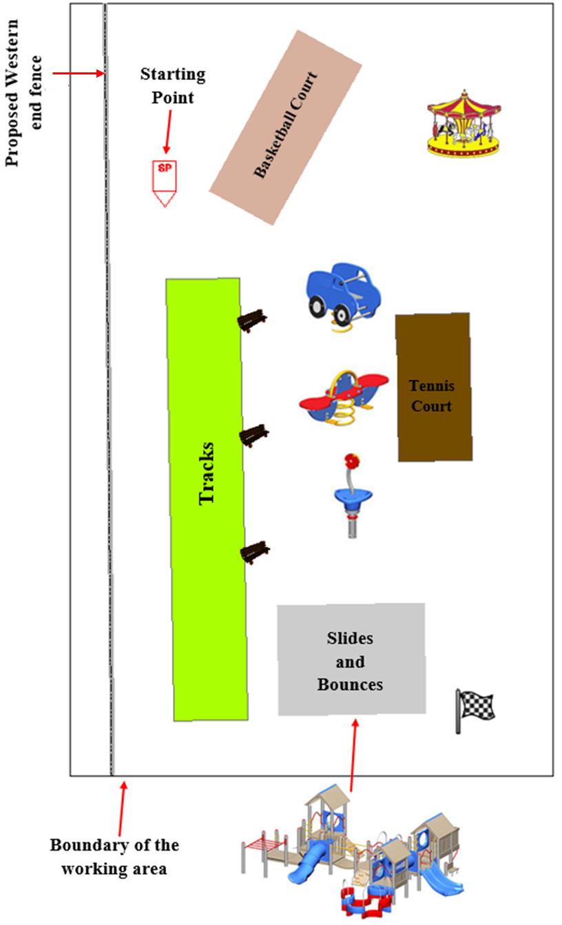
Figure 1. Rough draft of the playground plan
Good Luck!